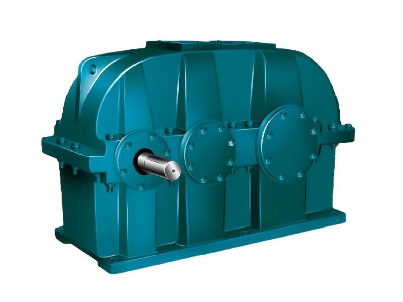
QJ Reducer
QJ Reducer Specifications:
- Models: QJR-D, QJRS-D, QJS-D
- Speed Ratios: 10, 12.5, 16, 20, 25, 31.5, 40, 50, 63, 80, 100, 125, 160, 200
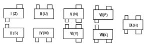
- Assembly Types: I, II, III, IV, V, VI, VII, VIII, IX
- Gear Shaft and Gear Materials: 42CrMo, 35CrMo
- Output Torque Range: 820 Nm to 33,500 Nm
- Custom Options: Non-standard customization available; production can be based on customer-provided drawings and specifications.
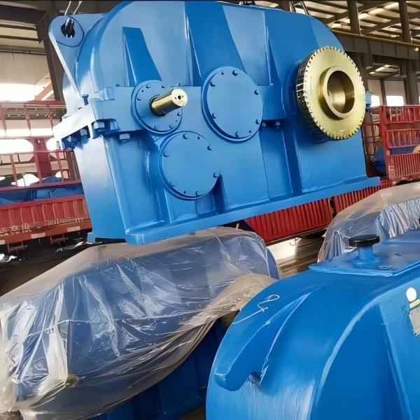
Overview of QJ Reducer
The QJ Reducer is designed for various crane mechanisms and is also widely applied in transmission systems across industries, including transportation, metallurgy, mining, chemical, and light industries.
Features
- Wide Reduction Ratio Range: Nominal speed ratios range from 10 to 200.
- High Mechanical Transmission Efficiency: Achieves 96% efficiency in two-stage transmission and 94% in three-stage.
- Smooth Operation and Low Noise: Provides stable performance with minimal noise levels.
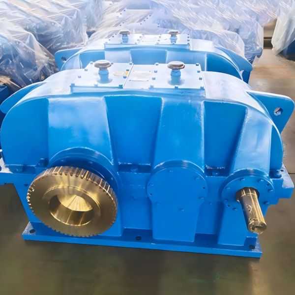
- High Durability and Load Capacity: Using 42CrMo and 35CrMo materials, forged and tempered for gear shafts and gears, the gearbox offers long service life and high load capacity.
- Easy Disassembly and Installation: Designed for ease of maintenance and installation.
Operating Conditions
- Peripheral gear speed not exceeding 16 m/s.
- High-speed shaft rotation not exceeding 1000 rpm.
- Ambient temperature ranging from -40°C to 45°C.
- Capable of bi-directional operation.
Models and Gear Ratios
| Type | Speed Ratio | |||||||
| QJR-D | 10 | 12.5 | 16 | 20 | 25 | 31.5 | ||
| QJS-D
QJRS-D |
40 | 50 | 63 | 80 | 100 | 125 | 160 | 200 |
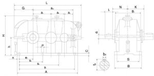
Installation Methods
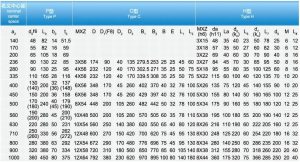
QJR-D Reducer Dimensions Table
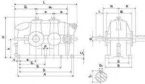
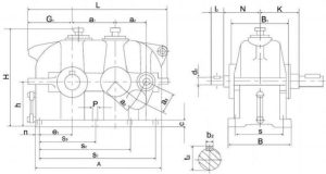
QJS-D Reducer Dimensions Table

QJRS-D Reducer Dimensions Table

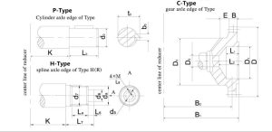
Output Shaft End Types and Dimensions
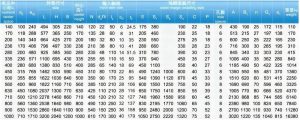
K Value for QJR-D, QJS-D, and QJRS-D Models
| Center distance | 140 | 170 | 200 | 236 | 280 | 335 | 400 | 450 | 500 | 560 | 630 | 710 | 800 | 900 | 1000 |
| K | 130 | 150 | 175 | 200 | 220 | 260 | 310 | 335 | 370 | 410 | 450 | 510 | 570 | 640 | 700 |
Maximum Permissible Radial Load on Gearbox Output Shaft End (at 950 rpm)
| Center distance | 140 | 170 | 200 | 236 | 280 | 335 | 400 | 450 | 500 | 560 | 630 | 710 | 800 | 900 | 1000 | |
| Maximum permissible radial load(KN) | R | 5 | 7 | 9 | 15 | 21 | 28 | 35 | 55 | 60 | 75 | 100 | 107 | 120 | 150 | 200 |
| S,RS | 5 | 8 | 10 | 15 | 30 | 37 | 55 | 64 | 93 | 120 | 150 | 170 | 200 | 240 | 270 | |