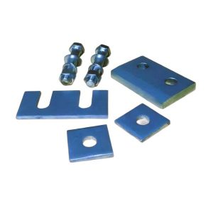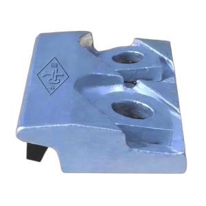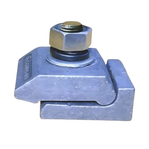
CGWK Rail Clip
Specifications of CGWK Rail Clip
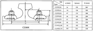
- Models: CGWK38, CGWK43, CGWK50, CGWK60, CGWK70, CGWK80, CGWK100, CGWK120
- Fixing Method: Welded base plate
Features of CGWK Rail Clip
Base Plate Welding
The CGWK base plate is welded to the upper flange of the steel crane beam using either two-side fillet welds or three-side wrap-around welds. This ensures that the horizontal lateral forces from the crane are evenly transmitted to the crane beam. In turn, this avoids the structural weaknesses that are typically caused by extensive drilling on the beam flange, thereby enhancing the overall stability of the crane system.
Spherical Hinged Connection
The base plate and the upper clamping plate are connected through a spherical hinge. This design allows for slight tilting under lateral forces, which effectively mitigates the impact of horizontal forces on the crane beam and braking systems. As a result, it helps in prolonging the lifespan of both the crane beam and braking systems by reducing the stress on these components.
Positioning Proximity
The CGWK base plate is strategically positioned approximately 1mm below the bottom edge of the rail. This precise positioning effectively restricts lateral rail movement, ensuring greater stability and reducing the risk of rail misalignment during operation.
Special Bolts for Stability
To optimize the load distribution on the fixing components, special bolts are utilized. These bolts enhance the system’s overall stability, and the upper clamping plate can be easily removed. This design feature significantly simplifies installation and maintenance, making the system more user-friendly and cost-effective.
Material and Strength
All fixing components are made from low-alloy high-strength steel, ensuring durability and strength. The M20 Grade 8.8 strength bolts are tightened to a torque of 220N·m, providing robust and secure fastening. Additionally, the system can withstand a maximum lateral force of 65kN at each wheel load point, which ensures its reliability in demanding crane operations.
Installation Instructions for CGWK Rail Clip
Rail Alignment
Before starting the installation, it is essential to align the rail according to the design specifications. This step is crucial to ensure the correct positioning of the rail and the proper function of the entire system.
Base Plate Positioning
Next, position the base plates along the rail direction at intervals of 500mm. Additionally, ensure that the perpendicular distance from the bolt center to the rail center (value a) is correctly positioned to ensure proper alignment and functionality.
Base Plate Welding
Once the base plates are positioned, proceed to weld the base plate to the crane beam using the specified welding method (either two-side or three-side welding). This step secures the base plates to the crane beam, forming a stable foundation for the rail clips.
Component Assembly
To assemble the CGWK rail clip, follow these steps in the order outlined below:
- Position the bolts to secure the components.
- Place the upper clamping plate onto the base plate.
- Add flat washers, spring washers, and nuts to the bolts.
- Finally, tighten the nuts to a torque of 220N·m, ensuring that the system is securely assembled and ready for use.
By following these instructions, the CGWK rail clip system will be installed efficiently, providing a reliable and durable solution for securing crane rails. The precise design, use of high-strength materials, and ease of installation make it an ideal choice for demanding industrial applications.